Home/CNC Machining
OUR SERVICES
CNC Machining and Contract CNC Manufacturing
CNC machining is the process of producing parts by removing material from raw stock with cutting tools on computer-controlled machines. At Memsa Havacılık, we plan drawing-compliant part production with 3, 4 and 5-axis solutions for companies that need contract CNC machining.

01CNC MACHINING
What Is Contract CNC Machining and Who Is It For?
Contract CNC machining means having parts produced externally by companies that lack their own machining infrastructure or want to supplement their existing capacity. Machine builders, mold makers, defense and aerospace suppliers and businesses that need spare parts use this model frequently.
The customer provides the technical drawing or 3D model; the manufacturer plans the process from material sourcing to machining and, if required, the inspection report. This allows the buyer to run parts of different geometries and quantities without investing in equipment.
APPLICATIONS
- Housings and body parts
- Flanges, plates and brackets
- Shafts, bushings and gear-like rotational parts
- Mold and fixture components
- Spare and replacement parts
- Prototype and pre-series parts
02SERVICES
Our CNC Machining Services
01 / 05
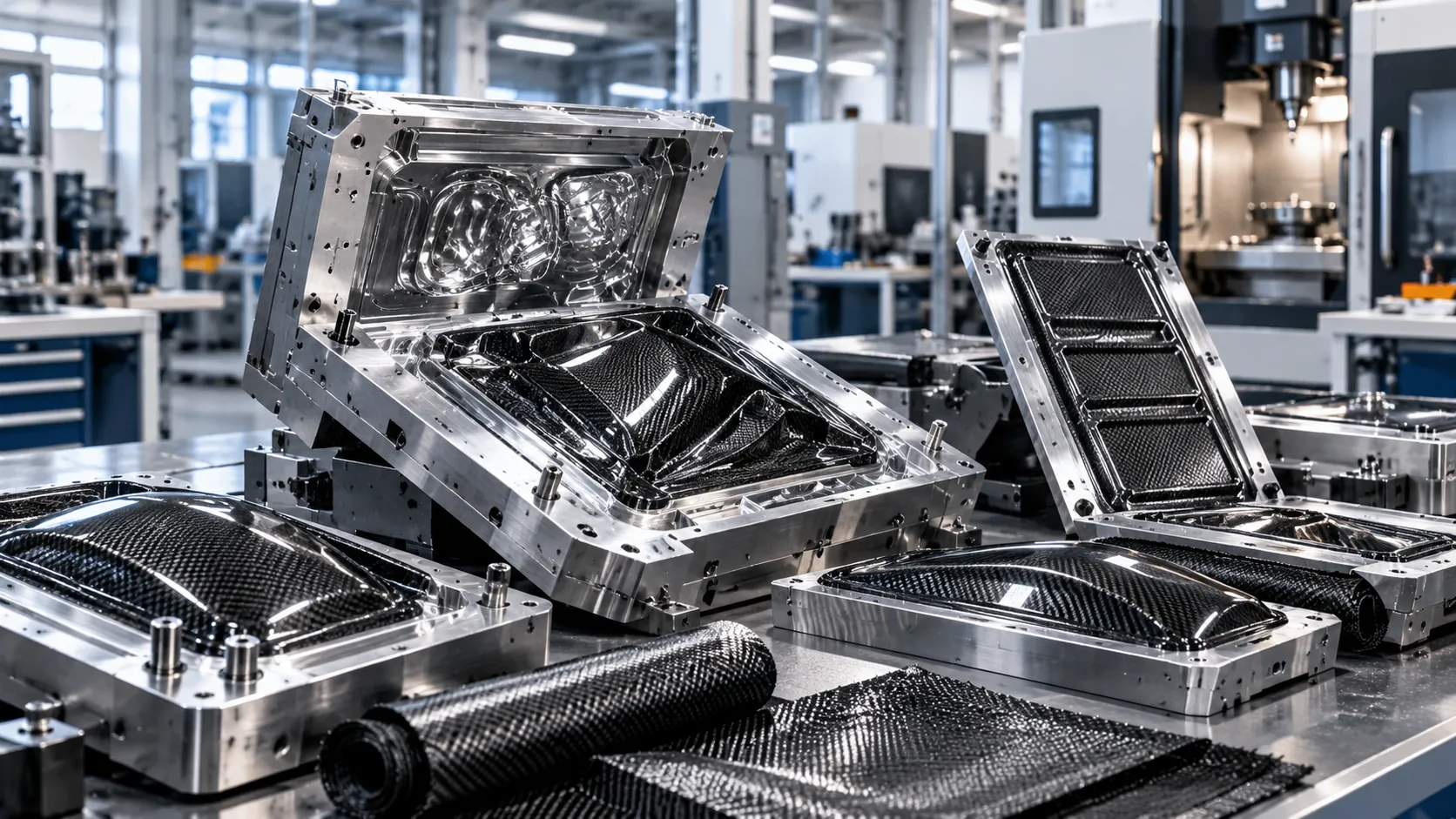
Composite and Carbon Fiber Molds
Layup tool, mold and pattern machining solutions for carbon fiber and composite part production.
EXPLORE

02 / 05
3-Axis CNC Machining
Efficient, repeatable 3-axis machining for prismatic parts, plates, flanges and mold components.
EXPLORE
03 / 05
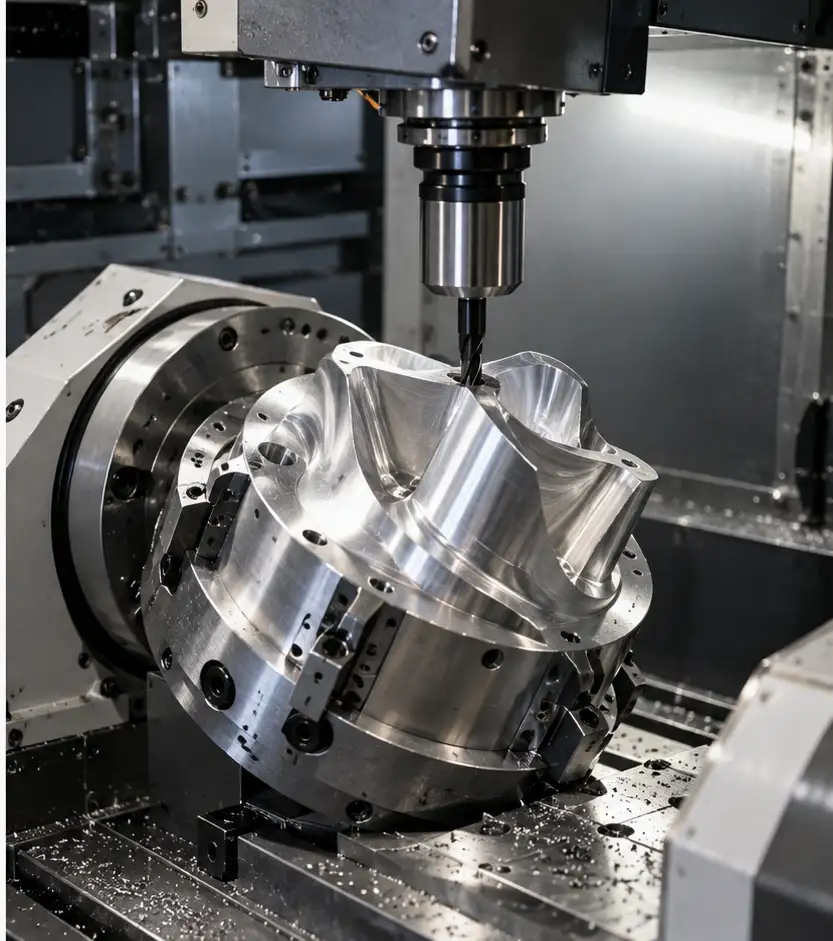
4-Axis CNC Machining
Single-setup machining of cylindrical and multi-face parts thanks to the rotary axis; keyways, holes and helical features.
EXPLORE
04 / 05
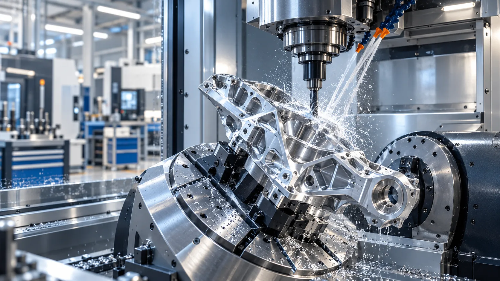
5-Axis CNC Machining
3+2 and simultaneous 5-axis machining of complex metal parts with fewer setups and high precision.
EXPLORE
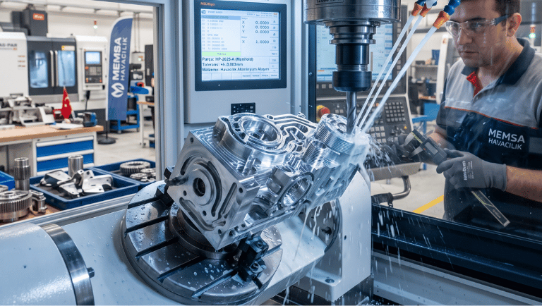
05 / 05
Precision Parts Manufacturing
Drawing-compliant production for parts that require tight tolerances, surface quality and measurement verification.
EXPLORE
03WHY MEMSA
Our Principles in Contract CNC Machining
01
3, 4 and 5-Axis Options
A 3-axis, 4-axis or 5-axis approach is evaluated according to the part geometry.
02
Prototype and Series Production
Production planning for different quantities, from one-off trials to recurring batches.
03
Drawing Compliance
Dimension, tolerance and surface requirements form the basis of the production and inspection plan.
04
Material Variety
Machining of materials such as aluminum, steel, stainless steel, titanium and engineering plastics.
05
Pre-Production Analysis
Manufacturing risks and alternative solutions are shared with the customer at the quotation stage.
06
Measurement Verification
Critical dimensions are inspected with measurement methods suited to the part requirements.
02
Our Approach with 3, 4 and 5-Axis Machines
The geometry of the part determines which axis configuration is suitable. While 3 axes are sufficient for prismatic parts accessible from one direction, a 4th axis can be advantageous for cylindrical parts or parts with several faces to machine, and 5 axes for parts with complex surfaces and multiple angles.
Machining surfaces in a single setup reduces the datum shift that can occur each time the part is removed and re-clamped, and makes it easier to hold positional tolerances between surfaces. Which approach is more economical is evaluated at the quotation stage depending on quantity, material and tolerance.
03
Prototype and Series Production
At the prototype stage, the goal is to validate the design quickly and revise it if necessary; flexible fixturing and fast programming therefore come to the fore for one-off or low-volume parts. Geometry or tolerance issues found on the drawing can be caught at this stage, before moving to series production.
In series production the priority is repeatability: parts are produced with the same method by keeping the validated CAM program, fixture and inspection plan. In small and medium batches, dedicated fixtures that shorten setup time can help reduce the cycle time per part.
Working from the same drawing, the same revision and the same inspection criteria from prototype to series supports consistency between parts. When the drawing revision changes, it is good practice to confirm with the customer that the current revision is used in production.
04
Technical Analysis and CAM Programming Before Production
Every job starts with a review of the technical drawing, material information and tolerance requirements. Points that carry manufacturing risk, such as deep pockets, thin walls, tight corner radii or hard materials, are shared with the customer at the quotation stage.
At the CAM stage, the roughing and finishing strategy, tool selection, fixturing and machining sequence are defined. Surfaces tied to the same dimensions are planned to be machined in the same setup whenever possible.
05
Measurement and Quality Control
For precision parts, verification matters as much as production. Coordinate measuring machines (CMM) collect points from the surface with touch or non-contact probes to build geometric elements such as cylinders and planes, enabling the evaluation of values such as roundness, flatness and perpendicularity.
Which measurement is performed with which method depends on the tolerance structure of the part and the documentation requested by the customer. Agreeing on the measurement method for critical dimensions before the order prevents mismatched expectations.
04MATERIALS
Materials We Machine
- Aluminum alloys (e.g. 6061, 7075, 2024)
- Carbon and alloy steels
- Stainless steels (e.g. 304, 316L, 17-4 PH)
- Titanium alloys (e.g. Ti-6Al-4V)
- Nickel-based superalloys (e.g. Inconel 718)
- Engineering plastics (e.g. POM, PEEK)
- Composite tooling boards and pattern materials
05PROCESS
Our Process from Drawing to Delivery
01
Technical Analysis
The technical drawing, 3D model, material, tolerance and quantity are reviewed; manufacturability and potential risks are clarified at the quotation stage.
02
CAM Programming
The machining strategy, toolpath and fixturing method suited to the part are defined; fixtures are designed when required.
03
CNC Production
The part is machined in the planned sequence on 3, 4 or 5-axis machines; critical dimensions are monitored during production.
04
Quality and Delivery
Dimensions on the drawing are inspected, the requested documents are prepared and the parts are shipped according to the agreed delivery plan.
06FAQ
Frequently Asked Questions
Contact us with your technical drawing, material and quantity; we will get back to you with an answer specific to your project.
Which files are needed for contract CNC machining?
A technical drawing (PDF) and, if possible, a 3D model such as STEP/IGES, together with material, quantity and tolerance information, are sufficient. Any missing information is clarified together at the quotation stage.
Can a single prototype part be produced?
Yes, production is planned for prototypes and one-off jobs. Lead time and cost are shared at the quotation stage depending on the part geometry and material.
How many axes does my part need?
It depends on the geometry. 3 axes may be sufficient for prismatic parts accessible from one direction; 4 axes are preferred for cylindrical or multi-face parts and 5 axes for complex surfaces. We review your drawing and make a recommendation.
How are general tolerances specified?
For dimensions without individual tolerances, ISO 2768 and a class letter (e.g. ISO 2768-m) are usually specified in the drawing title block. Critical dimensions are defined with separate tolerances on the drawing.
Get a Quote for Your Project
Send us your technical drawing for your contract CNC machining and prototype needs, and let us start the quotation process.